Blog

  • Connecting Solar Panels To MPPT Controller In Parallel

    Connecting Solar Panels To MPPT Controller In Parallel

    “Connecting solar panels to MPPT controller in parallel

    One of the key components of a solar power system is the Maximum Power Point Tracking (MPPT) controller, which plays a crucial role in optimizing energy output. In this article, we will explore the process of connecting solar panels to an MPPT controller in parallel, and provide a comprehensive guide on the benefits, requirements, and best practices for this setup.

    Connecting solar panels to MPPT controller in parallel

    Introduction to MPPT Controllers

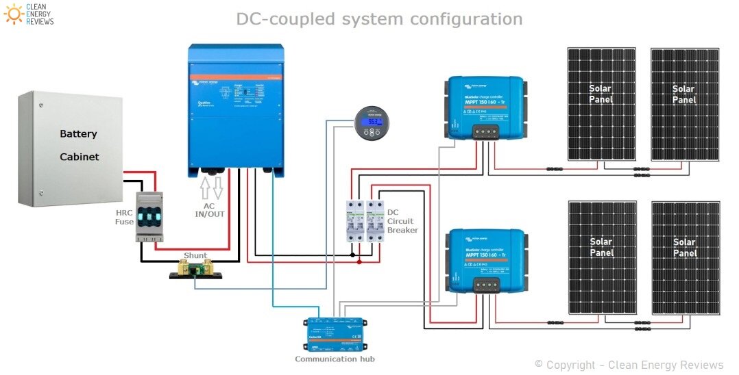
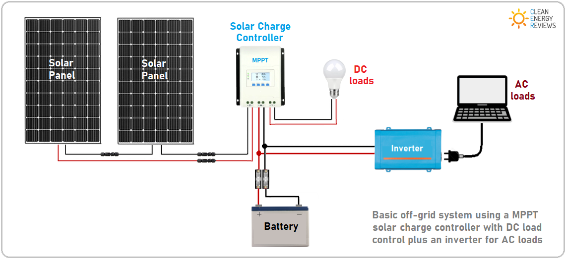
    Before we dive into the process of connecting solar panels to an MPPT controller in parallel, it’s essential to understand the basics of MPPT controllers. An MPPT controller is a device that tracks the maximum power point of a solar panel array and converts the DC voltage output to a suitable voltage for charging batteries or powering electrical loads. MPPT controllers are designed to optimize energy output by matching the solar panel’s voltage to the battery bank’s voltage, resulting in maximum power transfer.

    Benefits of Connecting Solar Panels in Parallel

    Connecting solar panels in parallel offers several benefits, including:

    1. Increased Power Output: By connecting solar panels in parallel, you can increase the total power output of your solar panel array. This is because each solar panel operates independently, and the total power output is the sum of the individual panel’s output.
    2. Improved System Reliability: When solar panels are connected in parallel, the system can continue to operate even if one or more panels are shaded or faulty. This is because the other panels can still produce power, reducing the impact of individual panel failures.
    3. Flexibility in System Design: Connecting solar panels in parallel allows for greater flexibility in system design. You can add or remove solar panels as needed, making it easier to upgrade or modify your system over time.

    Requirements for Connecting Solar Panels in Parallel

    Connecting solar panels to MPPT controller in parallel

    To connect solar panels to an MPPT controller in parallel, you’ll need to ensure that your system meets the following requirements:

    1. Compatible Solar Panels: Ensure that all solar panels are compatible with each other and have the same voltage rating. Mixing solar panels with different voltage ratings can lead to inefficient energy production and reduced system performance.
    2. MPPT Controller Compatibility: Choose an MPPT controller that is compatible with your solar panel array’s voltage and current ratings. The MPPT controller should also be able to handle the total power output of your solar panel array.
    3. Proper Wiring and Connections: Ensure that all wiring and connections are properly sized and secured to handle the maximum current output of your solar panel array.
    4. Connecting solar panels to MPPT controller in parallel

    Step-by-Step Guide to Connecting Solar Panels to MPPT Controller in Parallel

    To connect solar panels to an MPPT controller in parallel, follow these steps:

    1. Determine the Total Power Output: Calculate the total power output of your solar panel array by multiplying the individual panel’s power output.
    2. Connecting solar panels to MPPT controller in parallel

    3. Choose the Correct MPPT Controller: Select an MPPT controller that can handle the total power output of your solar panel array.
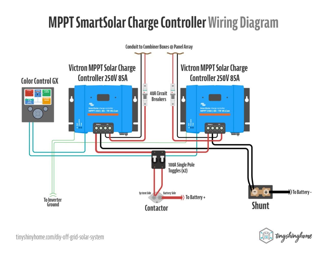
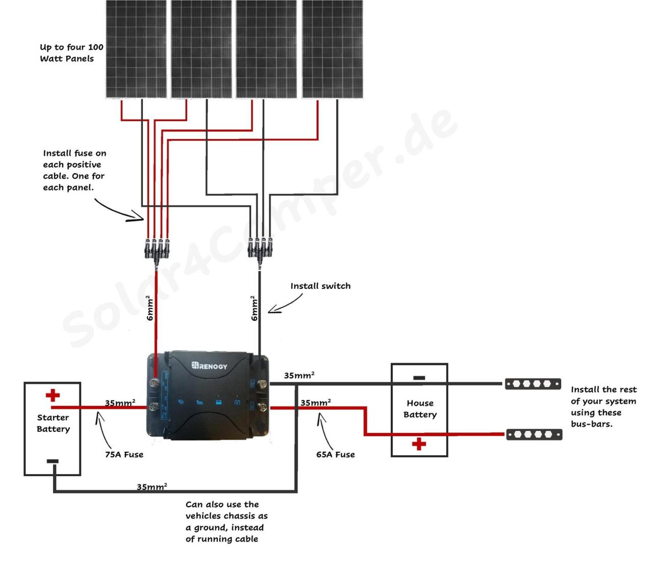
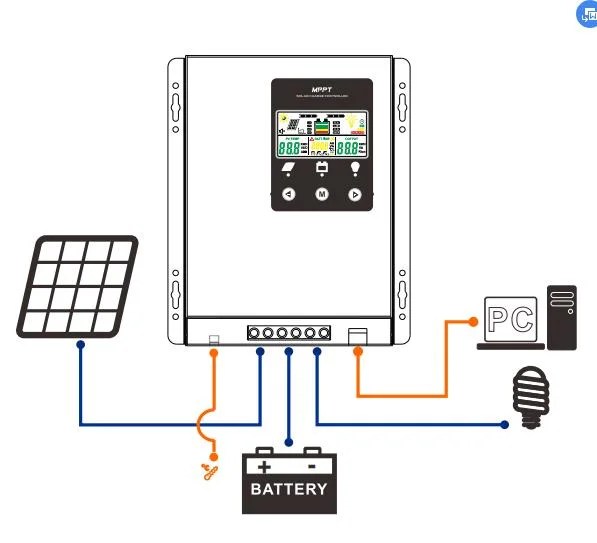
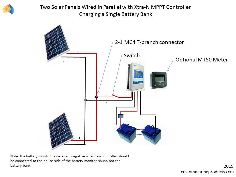
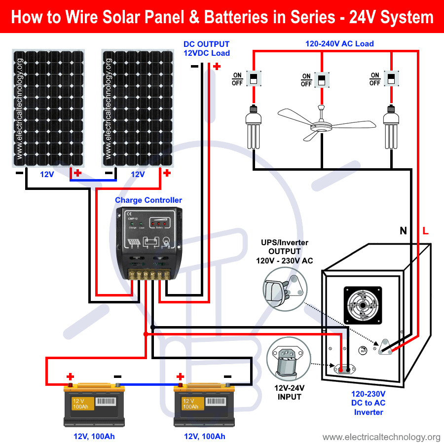
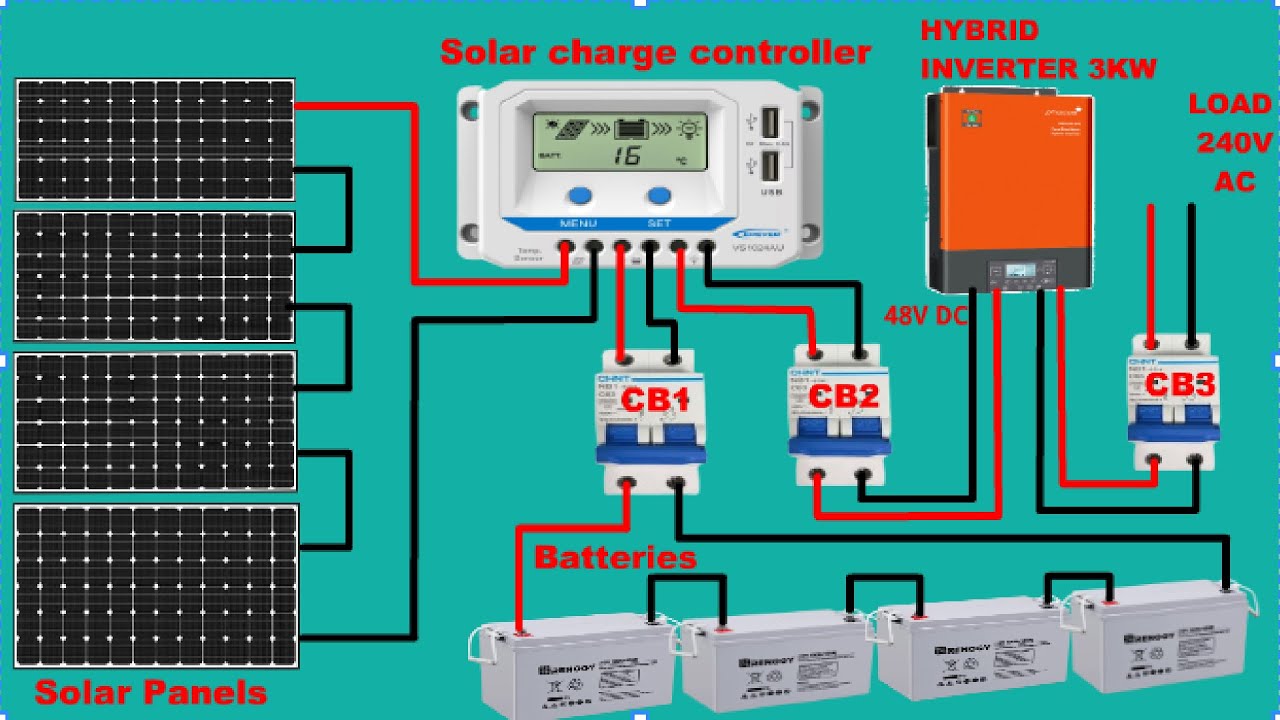
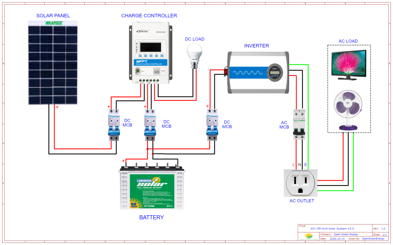
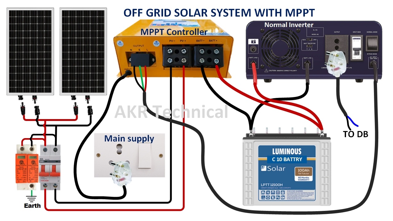
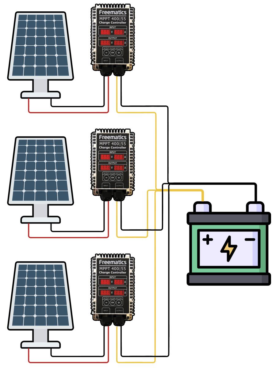
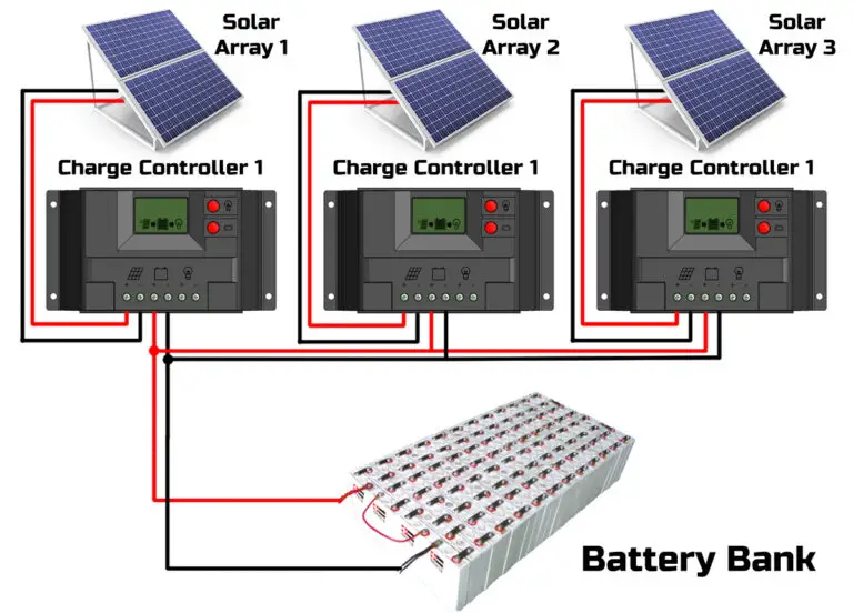
    4. Connect the Solar Panels in Parallel: Connect the positive terminal of each solar panel to a common positive busbar, and the negative terminal of each solar panel to a common negative busbar.
    5. Connect the Busbars to the MPPT Controller: Connect the positive busbar to the MPPT controller’s positive input terminal, and the negative busbar to the MPPT controller’s negative input terminal.
    6. Set the MPPT Controller Parameters: Configure the MPPT controller’s parameters, such as the battery voltage, charging current, and maximum power point tracking (MPPT) settings.
    7. Test the System: Test the system to ensure that it’s functioning correctly and producing the expected power output.

    Best Practices for Connecting Solar Panels in Parallel

    To ensure optimal performance and reliability, follow these best practices when connecting solar panels in parallel:

    1. Use Identical Solar Panels: Use identical solar panels to minimize variations in voltage and current output.
    2. Ensure Proper Wiring and Connections: Ensure that all wiring and connections are properly sized and secured to handle the maximum current output of your solar panel array.
    3. Monitor System Performance: Monitor system performance regularly to detect any issues or faults.
    4. Perform Regular Maintenance: Perform regular maintenance tasks, such as cleaning the solar panels and checking the connections, to ensure optimal system performance.

    Common Challenges and Troubleshooting

    When connecting solar panels to an MPPT controller in parallel, you may encounter some common challenges and issues. Here are some troubleshooting tips to help you resolve these issues:

    1. Low Power Output: Check the solar panel’s voltage and current output to ensure that they are within the expected range. Also, check the MPPT controller’s settings to ensure that they are configured correctly.
    2. High Voltage: Check the solar panel’s voltage output to ensure that it’s within the expected range. Also, check the MPPT controller’s settings to ensure that they are configured correctly.
    3. Connection Issues: Check the wiring and connections to ensure that they are properly sized and secured.

    Conclusion

    Connecting solar panels to an MPPT controller in parallel is a great way to increase power output, improve system reliability, and flexibility in system design. By following the steps outlined in this article, you can ensure a safe and efficient connection. Remember to choose compatible solar panels, select the correct MPPT controller, and follow best practices for connecting solar panels in parallel. With proper installation and maintenance, your solar power system can provide reliable and efficient energy for years to come.

    Additional Resources

    For more information on connecting solar panels to an MPPT controller in parallel, you can consult the following resources:

    1. Manufacturer’s Instructions: Consult the manufacturer’s instructions for the solar panels and MPPT controller to ensure that you’re following the recommended installation and configuration procedures.
    2. Online Forums and Communities: Join online forums and communities to connect with other solar power enthusiasts and professionals, and learn from their experiences.
    3. Technical Guides and Manuals: Consult technical guides and manuals to learn more about solar power systems, MPPT controllers, and parallel connections.

    By following the guidelines and best practices outlined in this article, you can create a reliable and efficient solar power system that meets your energy needs and provides a sustainable source of power for years to come.

    Connecting solar panels to MPPT controller in parallel

  • DIY Off-grid Solar Power System Wiring

    DIY Off-grid Solar Power System Wiring

    “DIY off-grid solar power system wiring

    However, setting up an off-grid solar power system can be a daunting task, especially when it comes to wiring. In this article, we will provide a step-by-step guide on how to wire a DIY off-grid solar power system, ensuring a safe and efficient installation.

    DIY off-grid solar power system wiring

    Introduction to Off-Grid Solar Power Systems

    An off-grid solar power system is a self-sufficient energy system that generates electricity from solar panels and stores it in batteries for later use. The system consists of several components, including solar panels, a charge controller, a battery bank, an inverter, and a load center. The wiring of these components is critical to ensure the system operates safely and efficiently.

    Components of an Off-Grid Solar Power System

    Before we dive into the wiring process, let’s take a look at the components involved in an off-grid solar power system:

    1. Solar Panels: These are the primary energy generators of the system, converting sunlight into direct current (DC) electricity.
    2. Charge Controller: This device regulates the flow of energy from the solar panels to the battery bank, preventing overcharging and ensuring the batteries are charged efficiently.
    3. Battery Bank: A group of deep cycle batteries that store excess energy generated by the solar panels for later use.
    4. Inverter: This device converts the DC electricity stored in the batteries into alternating current (AC) electricity, which is usable by household appliances.
    5. Load Center: The main electrical panel that distributes power to various loads, such as lights, refrigerators, and computers.
    6. DIY off-grid solar power system wiring

    Wiring Considerations

    Before starting the wiring process, it’s essential to consider the following factors:

    1. System Voltage: The voltage of the system, which is typically 12V, 24V, or 48V.
    2. DIY off-grid solar power system wiring

    3. System Current: The maximum current that will flow through the system, which depends on the size of the solar array and the load.
    4. Wire Size: The correct wire size to use, which depends on the system current and voltage.
    5. Grounding: A safe and reliable grounding system is essential to prevent electrical shock and ensure the system operates efficiently.

    Wiring the Solar Array

    DIY off-grid solar power system wiring

    The solar array is the first component to be wired in the off-grid solar power system. The following steps will guide you through the process:

    1. Connect the Solar Panels: Connect the positive and negative terminals of each solar panel to the corresponding terminals of the next panel, creating a series connection.
    2. Add a Combiner Box: Connect the series-connected solar panels to a combiner box, which combines the output of multiple strings of solar panels.
    3. Connect to the Charge Controller: Connect the combiner box to the charge controller, ensuring the correct polarity and voltage.

    Wiring the Charge Controller

    The charge controller is the next component to be wired. The following steps will guide you through the process:

    1. Connect the Charge Controller to the Battery Bank: Connect the output of the charge controller to the battery bank, ensuring the correct polarity and voltage.
    2. Connect the Charge Controller to the Solar Array: Connect the input of the charge controller to the solar array, ensuring the correct polarity and voltage.
    3. Configure the Charge Controller: Configure the charge controller to regulate the flow of energy from the solar array to the battery bank.

    Wiring the Battery Bank

    The battery bank is a critical component of the off-grid solar power system. The following steps will guide you through the wiring process:

    1. Connect the Batteries in Series: Connect the positive and negative terminals of each battery to the corresponding terminals of the next battery, creating a series connection.
    2. Connect the Battery Bank to the Inverter: Connect the output of the battery bank to the inverter, ensuring the correct polarity and voltage.
    3. Add a Battery Monitor: Install a battery monitor to track the state of charge and voltage of the battery bank.

    Wiring the Inverter

    The inverter is the final component to be wired. The following steps will guide you through the process:

    1. Connect the Inverter to the Battery Bank: Connect the input of the inverter to the battery bank, ensuring the correct polarity and voltage.
    2. Connect the Inverter to the Load Center: Connect the output of the inverter to the load center, ensuring the correct polarity and voltage.
    3. Configure the Inverter: Configure the inverter to convert the DC electricity from the battery bank to AC electricity for household use.

    Grounding and Bonding

    Grounding and bonding are critical components of an off-grid solar power system. The following steps will guide you through the process:

    1. Install a Grounding Rod: Install a grounding rod near the solar array and connect it to the system grounding point.
    2. Bond the System Components: Bond all system components, including the solar array, charge controller, battery bank, and inverter, to the system grounding point.
    3. Verify the Grounding System: Verify that the grounding system is safe and reliable, ensuring the system operates efficiently and preventing electrical shock.

    Final Inspection and Testing

    Before energizing the system, perform a final inspection and testing to ensure that:

    1. All connections are secure and correct: Verify that all connections are secure and correct, including polarity and voltage.
    2. The system is properly grounded: Verify that the grounding system is safe and reliable.
    3. The system operates efficiently: Verify that the system operates efficiently, generating and storing energy as expected.

    Conclusion

    Wiring a DIY off-grid solar power system requires careful planning and attention to detail. By following the steps outlined in this article, you can ensure a safe and efficient installation. Remember to always follow local electrical codes and regulations, and consider consulting a professional if you’re unsure about any aspect of the process. With the right knowledge and equipment, you can enjoy the benefits of renewable energy and reduce your reliance on traditional grid electricity.

    DIY off-grid solar power system wiring

  • Electric Vehicle Powertrain Component Layout

    Electric Vehicle Powertrain Component Layout

    The layout of these components plays a crucial role in determining the overall efficiency, performance, and reliability of the vehicle. In this article, we will delve into the world of electric vehicle powertrain component layout, exploring the different configurations, advantages, and challenges associated with each.

    electric vehicle powertrain component layout

    Introduction to Electric Vehicle Powertrains

    Electric vehicles use electric motors, powered by batteries, to propel the vehicle. The powertrain consists of several key components, including:

    1. Electric Motor: Converts electrical energy from the battery into mechanical energy to propel the vehicle.
    2. Battery Pack: Stores electrical energy to power the motor.
    3. Power Electronics: Controls the flow of electrical energy between the battery and motor.
    4. Transmission: Transfers mechanical energy from the motor to the wheels.
    5. Thermal Management System: Regulates the temperature of the powertrain components.

    Powertrain Component Layout Configurations

    electric vehicle powertrain component layout

    There are several powertrain component layout configurations used in electric vehicles, each with its own advantages and disadvantages. Some of the most common configurations include:

    1. Central Motor Configuration: In this configuration, the electric motor is located at the center of the vehicle, with the battery pack and power electronics located nearby. This configuration is commonly used in rear-wheel drive (RWD) and all-wheel drive (AWD) vehicles.
    2. Axle-Mounted Motor Configuration: In this configuration, the electric motor is integrated into the axle, with the battery pack and power electronics located elsewhere in the vehicle. This configuration is commonly used in front-wheel drive (FWD) vehicles.
    3. Distributed Motor Configuration: In this configuration, multiple electric motors are used, each located near a wheel or axle. This configuration is commonly used in high-performance and AWD vehicles.
    4. electric vehicle powertrain component layout

    5. Modular Powertrain Configuration: In this configuration, the powertrain components are packaged into a single module, which can be easily integrated into different vehicle platforms. This configuration is commonly used in vehicle platforms designed for multiple powertrain options.

    Advantages and Disadvantages of Each Configuration

    Each powertrain component layout configuration has its own advantages and disadvantages. Some of the key benefits and drawbacks include:

      electric vehicle powertrain component layout

    • Central Motor Configuration:
      • Advantages: Simple and compact design, easy to package, and low cost.
      • Disadvantages: Limited flexibility, potential for motor noise and vibration, and heat management challenges.
    • Axle-Mounted Motor Configuration:
      • Advantages: Improved packaging, reduced motor noise and vibration, and enhanced thermal management.
      • Disadvantages: Increased complexity, higher cost, and potential for reduced motor efficiency.
    • Distributed Motor Configuration:
      • Advantages: Improved traction, enhanced performance, and increased flexibility.
      • Disadvantages: Increased complexity, higher cost, and potential for reduced motor efficiency.
    • Modular Powertrain Configuration:
      • Advantages: Easy integration, reduced development time and cost, and improved flexibility.
      • Disadvantages: Potential for reduced performance, increased weight, and thermal management challenges.

    Thermal Management System Integration

    The thermal management system (TMS) plays a critical role in regulating the temperature of the powertrain components. The TMS consists of several components, including:

    1. Coolant: A liquid or gas used to transfer heat from the powertrain components to the TMS.
    2. Heat Exchanger: A device used to transfer heat from the coolant to the ambient air or a secondary coolant loop.
    3. Pumps and Fans: Used to circulate the coolant and provide airflow to the heat exchanger.

    The TMS can be integrated into the powertrain component layout in several ways, including:

    1. Air-Cooled TMS: Uses airflow to cool the powertrain components.
    2. Liquid-Cooled TMS: Uses a liquid coolant to cool the powertrain components.
    3. Hybrid TMS: Combines air-cooled and liquid-cooled TMS components.

    Challenges and Considerations

    The powertrain component layout configuration can have a significant impact on the overall performance, efficiency, and reliability of the vehicle. Some of the key challenges and considerations include:

    1. Packaging and Integration: The powertrain components must be packaged and integrated into the vehicle platform, while minimizing weight, cost, and complexity.
    2. Thermal Management: The TMS must be designed to regulate the temperature of the powertrain components, while minimizing weight, cost, and complexity.
    3. Noise and Vibration: The powertrain components can generate noise and vibration, which must be mitigated to ensure a comfortable and quiet ride.
    4. Electromagnetic Compatibility: The powertrain components can generate electromagnetic interference (EMI), which must be mitigated to ensure proper operation of the vehicle systems.

    Conclusion

    The electric vehicle powertrain component layout is a complex system that requires careful consideration of multiple factors, including packaging, thermal management, noise and vibration, and electromagnetic compatibility. The different powertrain component layout configurations each have their own advantages and disadvantages, and the choice of configuration depends on the specific vehicle application and requirements. By understanding the challenges and considerations associated with the powertrain component layout, vehicle manufacturers can design and develop more efficient, reliable, and high-performance electric vehicles.

    Future Developments

    As the electric vehicle market continues to evolve, we can expect to see new and innovative powertrain component layout configurations emerge. Some of the potential future developments include:

    1. Advanced Materials and Designs: New materials and designs, such as carbon fiber and advanced composites, can be used to reduce weight and improve packaging.
    2. Modular and Scalable Designs: Modular and scalable designs can be used to simplify the development and production process, while improving flexibility and reducing cost.
    3. Thermal Management System Advances: Advances in TMS technology, such as more efficient heat exchangers and pumps, can be used to improve thermal management and reduce weight and cost.
    4. Autonomous and Connected Vehicle Technologies: Autonomous and connected vehicle technologies can be integrated into the powertrain component layout, enabling new features and capabilities, such as advanced driver assistance systems (ADAS) and vehicle-to-everything (V2X) communication.

    By embracing these future developments and continuing to innovate and improve the powertrain component layout, the electric vehicle industry can drive growth, efficiency, and sustainability, while providing customers with more efficient, reliable, and high-performance vehicles.

    electric vehicle powertrain component layout

  • MPPT Wiring Diagram For Solar Power Systems

    MPPT Wiring Diagram For Solar Power Systems

    “MPPT wiring diagram for solar power systems

    One of the key components of a solar power system is the Maximum Power Point Tracking (MPPT) controller, which plays a crucial role in optimizing energy harvesting and efficiency. In this article, we will delve into the world of MPPT wiring diagrams, exploring their importance, key components, and step-by-step instructions for creating a safe and efficient solar power system.

    MPPT wiring diagram for solar power systems

    What is MPPT and Why is it Important?

    Maximum Power Point Tracking (MPPT) is a technique used to optimize the energy output of a solar panel system. It involves tracking the maximum power point of the solar array, which is the point at which the array produces the most power. MPPT controllers work by adjusting the voltage and current output of the solar array to match the maximum power point, ensuring that the system operates at maximum efficiency.

    MPPT is essential for solar power systems because it:

    1. Maximizes energy output: By tracking the maximum power point, MPPT controllers can increase energy output by up to 30% compared to traditional pulse-width modulation (PWM) controllers.
    2. Improves system efficiency: MPPT controllers can optimize system performance, reducing energy losses and heat generation.
    3. Enhances system reliability: By operating at maximum efficiency, MPPT controllers can reduce the risk of overheating and component failure.

    Key Components of an MPPT Wiring Diagram

    An MPPT wiring diagram typically consists of the following components:

    MPPT wiring diagram for solar power systems

    1. Solar array: The solar array consists of multiple solar panels connected in series and/or parallel to achieve the desired voltage and current output.
    2. MPPT controller: The MPPT controller is the brain of the system, responsible for tracking the maximum power point and adjusting the voltage and current output accordingly.
    3. Battery bank: The battery bank stores excess energy generated by the solar array for later use.
    4. Inverter/charger: The inverter/charger converts DC power from the solar array and battery bank to AC power for household use.
    5. MPPT wiring diagram for solar power systems

    6. Grounding system: The grounding system provides a safe path to ground for electrical currents and protects against shock and electrocution.

    Step-by-Step Guide to Creating an MPPT Wiring Diagram

    Creating an MPPT wiring diagram requires careful planning and attention to detail. Here’s a step-by-step guide to help you get started:

      MPPT wiring diagram for solar power systems

    1. Determine the system specifications: Determine the voltage and current requirements of your solar power system, including the number of solar panels, battery bank capacity, and inverter/charger rating.
    2. Choose the MPPT controller: Select an MPPT controller that matches your system specifications and is compatible with your solar array and battery bank.
    3. Design the solar array: Design the solar array to achieve the desired voltage and current output. Ensure that the array is properly sized and configured for the MPPT controller.
    4. Connect the solar array to the MPPT controller: Connect the solar array to the MPPT controller, ensuring that the polarity is correct and the connections are secure.
    5. Connect the MPPT controller to the battery bank: Connect the MPPT controller to the battery bank, ensuring that the polarity is correct and the connections are secure.
    6. Connect the battery bank to the inverter/charger: Connect the battery bank to the inverter/charger, ensuring that the polarity is correct and the connections are secure.
    7. Ground the system: Ground the system to ensure safety and protect against shock and electrocution.

    Example MPPT Wiring Diagram

    Here’s an example MPPT wiring diagram for a small solar power system:

    • Solar array: 4 x 250W solar panels connected in series (1000W total)
    • MPPT controller: 40A MPPT controller with built-in grounding
    • Battery bank: 24V 400Ah deep cycle battery bank
    • Inverter/charger: 2000W 24V inverter/charger

    The wiring diagram would show the following connections:

    • Solar array positive terminal connected to MPPT controller positive terminal
    • Solar array negative terminal connected to MPPT controller negative terminal
    • MPPT controller positive terminal connected to battery bank positive terminal
    • MPPT controller negative terminal connected to battery bank negative terminal
    • Battery bank positive terminal connected to inverter/charger positive terminal
    • Battery bank negative terminal connected to inverter/charger negative terminal
    • Grounding system connected to MPPT controller and battery bank

    Safety Considerations and Best Practices

    When working with electrical systems, safety is paramount. Here are some safety considerations and best practices to keep in mind:

    1. Use proper wiring and connectors: Use high-quality wiring and connectors to ensure secure connections and minimize the risk of electrical shock.
    2. Follow manufacturer instructions: Follow the manufacturer’s instructions for the MPPT controller, solar array, and other system components.
    3. Use grounding and bonding: Use grounding and bonding to ensure that the system is properly grounded and protected against electrical shock.
    4. Test the system: Test the system before use to ensure that it is functioning correctly and safely.
    5. Regular maintenance: Regularly inspect and maintain the system to ensure that it continues to operate safely and efficiently.

    Conclusion

    MPPT wiring diagrams are a critical component of solar power systems, ensuring that the system operates at maximum efficiency and safety. By understanding the key components, following a step-by-step guide, and adhering to safety considerations and best practices, you can create a safe and efficient solar power system that meets your energy needs. Remember to always follow manufacturer instructions and consult with a professional if you’re unsure about any aspect of the system design or installation. With the right knowledge and expertise, you can harness the power of the sun to generate clean, renewable energy for your home or business.

    MPPT wiring diagram for solar power systems

  • Main Components Of Electric Vehicle

    Main Components Of Electric Vehicle

    With governments setting targets to phase out internal combustion engines and manufacturers investing heavily in EV technology, the demand for electric vehicles is on the rise. But have you ever wondered what makes an electric vehicle tick? In this article, we will delve into the main components of an electric vehicle, exploring their functions, benefits, and the role they play in making EVs a viable alternative to traditional gasoline-powered cars.

    main components of electric vehicle

    1. Electric Motor

    The electric motor is the heart of an electric vehicle, responsible for converting electrical energy into mechanical energy to propel the vehicle forward. There are several types of electric motors used in EVs, including:

    • DC Brushless Motor: This type of motor uses a DC power source and is commonly used in hybrid and plug-in hybrid electric vehicles.
    • AC Induction Motor: This type of motor uses an AC power source and is commonly used in battery electric vehicles (BEVs).
    • Permanent Magnet Motor: This type of motor uses a permanent magnet as the rotor and is commonly used in high-performance EVs.

    Electric motors have several advantages over traditional internal combustion engines, including higher efficiency, lower maintenance, and reduced noise pollution. They also provide instant torque, making EVs accelerate quickly and smoothly.

    2. Battery Pack

    The battery pack is a critical component of an electric vehicle, providing the energy storage needed to power the electric motor. Battery packs are typically made up of multiple individual battery cells, which are connected in series and parallel to provide the required voltage and capacity.

    main components of electric vehicle

    • Lithium-Ion Batteries: These are the most common type of battery used in EVs, offering high energy density, long cycle life, and relatively low self-discharge rates.
    • Nickel-Metal Hydride Batteries: These batteries are less common in EVs but are still used in some hybrid vehicles.
    • Lead-Acid Batteries: These batteries are rarely used in EVs due to their low energy density and short cycle life.

    main components of electric vehicle

    Battery packs are designed to be durable and long-lasting, with some manufacturers offering warranties of up to 8 years or 100,000 miles. However, battery degradation over time can affect an EV’s range and performance.

    3. Power Electronics

    Power electronics play a crucial role in controlling the flow of electrical energy between the battery pack, electric motor, and other components of the vehicle. The main power electronics components include:

    • Inverter: This component converts DC power from the battery pack into AC power for the electric motor.
    • main components of electric vehicle

    • Converter: This component converts AC power from the electric motor into DC power for the battery pack during regenerative braking.
    • Charging System: This component controls the flow of energy during charging, ensuring the battery pack is charged safely and efficiently.

    Power electronics are designed to be highly efficient and reliable, with some manufacturers using advanced technologies such as silicon carbide (SiC) and gallium nitride (GaN) to reduce losses and improve performance.

    4. Transmission and Drivetrain

    The transmission and drivetrain of an electric vehicle are designed to be efficient and reliable, with some EVs using a single-speed or multi-speed transmission. The main components include:

    • Transmission: This component transmits power from the electric motor to the wheels, with some EVs using a fixed gear ratio and others using a variable gear ratio.
    • Differential: This component enables the wheels to rotate at different speeds, improving traction and stability.
    • Driveshaft: This component connects the transmission to the wheels, transmitting power and torque.

    The transmission and drivetrain of an EV are designed to be compact and lightweight, with some manufacturers using advanced materials and technologies to reduce energy losses and improve efficiency.

    5. Charging System

    The charging system of an electric vehicle is designed to be safe, efficient, and convenient, with several charging options available:

    • Level 1 Charging: This type of charging uses a standard 120V household outlet and is suitable for low-mileage drivers.
    • Level 2 Charging: This type of charging uses a 240V charging station and is suitable for most EV owners.
    • DC Fast Charging: This type of charging uses a high-power DC charging station and can charge an EV to 80% in under 30 minutes.

    Charging systems are designed to be user-friendly, with many EVs offering advanced charging features such as scheduled charging, remote charging, and charging station mapping.

    6. Battery Management System (BMS)

    The battery management system (BMS) is a critical component of an electric vehicle, responsible for monitoring and controlling the battery pack’s state of charge, state of health, and temperature. The BMS ensures the battery pack operates within a safe and efficient range, preventing overcharging, over-discharging, and overheating.

    • Cell Balancing: This function ensures that all battery cells are charged and discharged evenly, preventing any single cell from becoming overcharged or undercharged.
    • State of Charge (SoC) Estimation: This function estimates the battery pack’s state of charge, enabling the vehicle to provide accurate range estimates and prevent over-discharging.
    • Thermal Management: This function monitors and controls the battery pack’s temperature, preventing overheating and ensuring optimal performance.

    The BMS is a sophisticated system that uses advanced algorithms and sensors to monitor and control the battery pack, ensuring the EV operates safely and efficiently.

    7. Electrical Architecture

    The electrical architecture of an electric vehicle is designed to be efficient, reliable, and scalable, with several components working together to provide power to the vehicle’s systems:

    • High-Voltage System: This system provides power to the electric motor, transmission, and other high-voltage components.
    • Low-Voltage System: This system provides power to the vehicle’s accessories, such as the lights, radio, and wipers.
    • Communication Network: This network enables communication between the vehicle’s systems, including the BMS, transmission, and electric motor.

    The electrical architecture of an EV is designed to be modular and flexible, with many manufacturers using standardized components and interfaces to simplify production and reduce costs.

    Conclusion

    In conclusion, the main components of an electric vehicle work together to provide a safe, efficient, and enjoyable driving experience. From the electric motor to the battery pack, power electronics, transmission, and charging system, each component plays a critical role in making EVs a viable alternative to traditional gasoline-powered cars. As technology continues to evolve, we can expect to see even more efficient, reliable, and affordable electric vehicles on the road, helping to reduce our dependence on fossil fuels and create a more sustainable transportation system for the future.

    Future Outlook

    As the world continues to shift towards electrification, we can expect to see significant advancements in electric vehicle technology. Some of the trends and developments that are likely to shape the future of EVs include:

    • Improved Battery Technology: Advances in battery technology are expected to improve energy density, reduce costs, and increase range.
    • Increased Adoption of Autonomous Vehicles: Autonomous vehicles are likely to play a significant role in the future of transportation, with many manufacturers investing heavily in autonomous EV technology.
    • Growing Demand for Sustainable Energy: As concern for the environment grows, there will be an increasing demand for sustainable energy sources, such as solar and wind power, to charge EVs.

    Overall, the future of electric vehicles looks bright, with many manufacturers, governments, and consumers working together to create a more sustainable and environmentally friendly transportation system. As technology continues to evolve, we can expect to see even more exciting developments in the world of electric vehicles, helping to shape a cleaner, more efficient, and more enjoyable driving experience for generations to come.

    main components of electric vehicle

  • How To Read An EV Components Diagram

    How To Read An EV Components Diagram

    One of the best ways to gain insight into the inner workings of an EV is by reading its components diagram. In this article, we will guide you through the process of reading an EV components diagram, helping you to better understand the various components, their functions, and how they interact with each other.

    how to read an EV components diagram

    Introduction to EV Components Diagrams

    An EV components diagram is a visual representation of the various components that make up an electric vehicle. It is a complex diagram that shows the relationships between the different components, including the battery, electric motor, power electronics, and other systems. The diagram is typically made up of various symbols, lines, and labels that represent the different components and their connections.

    Understanding the Symbols and Notations

    Before diving into the diagram, it’s essential to understand the symbols and notations used. Here are some common symbols and notations you’ll encounter:

    • Rectangles and boxes: These represent individual components, such as the battery, electric motor, or power electronics.
    • Lines and arrows: These represent the connections between components, indicating the flow of energy, signals, or data.
    • Labels and text: These provide additional information about the components, such as their names, functions, or specifications.
    • Colors and shading: These are used to differentiate between different types of components or to highlight specific features.

    how to read an EV components diagram

    Breaking Down the Diagram

    To read an EV components diagram, it’s essential to break it down into its individual sections. Here are the main sections you’ll typically find:

    1. Battery Management System (BMS): This section shows the battery, its management system, and the connections to the rest of the vehicle.
    2. Electric Motor and Power Electronics: This section displays the electric motor, power electronics, and their connections to the battery and other systems.
    3. how to read an EV components diagram

    4. Powertrain and Transmission: This section shows the powertrain, transmission, and their connections to the electric motor and other systems.
    5. Thermal Management System: This section displays the thermal management system, including the cooling and heating systems.
    6. Electrical and Electronic Systems: This section shows the electrical and electronic systems, including the wiring, connectors, and control units.

    Reading the Diagram

    how to read an EV components diagram

    Now that you’ve broken down the diagram into its individual sections, it’s time to read it. Here’s a step-by-step guide:

    1. Start with the battery: The battery is the heart of the EV, and understanding its connections and management system is crucial. Look for the battery symbol and follow the lines and arrows to see how it connects to the rest of the vehicle.
    2. Follow the energy flow: Trace the lines and arrows to see how energy flows from the battery to the electric motor and other systems.
    3. Identify the power electronics: The power electronics are responsible for controlling the flow of energy between the battery, electric motor, and other systems. Look for the power electronics symbol and follow the connections to understand its role.
    4. Understand the thermal management system: The thermal management system is critical for maintaining the optimal operating temperature of the battery and other components. Look for the thermal management system symbol and follow the connections to understand how it works.
    5. Examine the electrical and electronic systems: The electrical and electronic systems are responsible for controlling the various functions of the vehicle, such as the lights, wipers, and infotainment system. Look for the electrical and electronic systems symbol and follow the connections to understand how they interact with other systems.

    Common Components and Their Functions

    Here are some common components you’ll find in an EV components diagram, along with their functions:

    1. Battery: The battery is the energy storage system of the EV, providing the power necessary to propel the vehicle.
    2. Electric Motor: The electric motor is responsible for converting the electrical energy from the battery into mechanical energy, propelling the vehicle.
    3. Power Electronics: The power electronics control the flow of energy between the battery, electric motor, and other systems.
    4. Inverter: The inverter converts the DC power from the battery into AC power for the electric motor.
    5. DC-DC Converter: The DC-DC converter converts the high-voltage DC power from the battery to low-voltage DC power for the vehicle’s accessories.
    6. Charging System: The charging system is responsible for replenishing the battery’s energy from an external power source.

    Tips and Tricks

    Here are some tips and tricks to help you read an EV components diagram:

    1. Start with a simple diagram: If you’re new to EV components diagrams, start with a simple diagram and gradually move to more complex ones.
    2. Use online resources: There are many online resources available that can help you understand EV components diagrams, including tutorials, videos, and forums.
    3. Look for patterns: Look for patterns and relationships between components to help you understand the diagram.
    4. Use a legend: If the diagram includes a legend, use it to help you understand the symbols and notations.
    5. Practice, practice, practice: The more you practice reading EV components diagrams, the more comfortable you’ll become with the symbols, notations, and components.

    Conclusion

    Reading an EV components diagram can seem daunting at first, but with practice and patience, you can gain a deep understanding of the various components and their functions. By breaking down the diagram into its individual sections, understanding the symbols and notations, and following the energy flow, you can unlock the secrets of the EV components diagram. Remember to start with a simple diagram, use online resources, look for patterns, and practice, practice, practice. With this guide, you’ll be well on your way to becoming an expert in reading EV components diagrams and gaining a deeper understanding of the electric vehicles that are revolutionizing the automotive industry.

    how to read an EV components diagram

  • Wiring Solar Panels With MPPT Controller And Battery Storage

    “Wiring solar panels with MPPT controller and battery storage

    A well-designed solar power system with Maximum Power Point Tracking (MPPT) controller and battery storage can significantly reduce energy costs and provide a reliable source of electricity. In this article, we will delve into the details of wiring solar panels with an MPPT controller and battery storage, and explore the benefits and best practices of such a system.

    Wiring solar panels with MPPT controller and battery storage

    Introduction to Solar Power Systems

    A solar power system consists of solar panels, a charge controller, a battery bank, and an inverter. The solar panels convert sunlight into DC electricity, which is then sent to the charge controller. The charge controller regulates the flow of energy from the solar panels to the battery bank, ensuring that the batteries are not overcharged or undercharged. The battery bank stores excess energy generated by the solar panels during the day for use during the night or on cloudy days. The inverter converts the DC electricity stored in the batteries to AC electricity, which can be used to power appliances and equipment.

    Maximum Power Point Tracking (MPPT) Controller

    A Maximum Power Point Tracking (MPPT) controller is a critical component of a solar power system. Its primary function is to optimize energy harvest from the solar panels by tracking the maximum power point (MPP) of the solar array. The MPP is the point at which the solar array produces the maximum power, taking into account the voltage and current output of the solar panels. The MPPT controller continuously monitors the voltage and current output of the solar array and adjusts the operating point of the solar panels to ensure maximum energy production.

    MPPT controllers offer several advantages over traditional pulse width modulation (PWM) controllers, including:

    1. Higher Efficiency: MPPT controllers can increase energy production by up to 30% compared to PWM controllers.
    2. Improved Charging: MPPT controllers can charge batteries faster and more efficiently, reducing charging time and increasing battery lifespan.
    3. Flexibility: MPPT controllers can handle a wide range of solar panel configurations and battery types.

    Wiring solar panels with MPPT controller and battery storage

    Wiring Solar Panels with MPPT Controller

    When wiring solar panels with an MPPT controller, it is essential to follow proper wiring and configuration guidelines to ensure safe and efficient operation. Here are some steps to follow:

    1. Determine the Solar Panel Configuration: Determine the number of solar panels to be connected in series and parallel to achieve the desired voltage and current output.
    2. Choose the Correct Wire Size: Choose wire sizes that can handle the maximum current output of the solar panels and the MPPT controller.
    3. Wiring solar panels with MPPT controller and battery storage

    4. Connect Solar Panels in Series: Connect solar panels in series to achieve the desired voltage output. Ensure that the voltage output of the solar panels matches the input voltage range of the MPPT controller.
    5. Connect Solar Panels in Parallel: Connect solar panels in parallel to increase the current output. Ensure that the current output of the solar panels does not exceed the maximum current rating of the MPPT controller.
    6. Connect the MPPT Controller: Connect the MPPT controller to the solar panels and the battery bank. Ensure that the polarity of the connections is correct, and the wiring is secure and protected from the elements.

    Battery Storage

    Wiring solar panels with MPPT controller and battery storage

    Battery storage is a critical component of a solar power system, allowing excess energy generated by the solar panels to be stored for later use. Here are some factors to consider when selecting a battery bank:

    1. Depth of Discharge (DOD): Choose batteries with a high DOD to maximize energy storage capacity.
    2. Cycle Life: Choose batteries with a high cycle life to ensure long-term reliability and performance.
    3. Self-Discharge Rate: Choose batteries with a low self-discharge rate to minimize energy loss during storage.
    4. Battery Type: Choose between lead-acid, lithium-ion, or other battery types based on cost, performance, and environmental factors.

    Wiring the Battery Bank

    When wiring the battery bank, it is essential to follow proper wiring and configuration guidelines to ensure safe and efficient operation. Here are some steps to follow:

    1. Determine the Battery Configuration: Determine the number of batteries to be connected in series and parallel to achieve the desired voltage and capacity.
    2. Choose the Correct Wire Size: Choose wire sizes that can handle the maximum current output of the battery bank and the MPPT controller.
    3. Connect Batteries in Series: Connect batteries in series to achieve the desired voltage output. Ensure that the voltage output of the batteries matches the input voltage range of the MPPT controller.
    4. Connect Batteries in Parallel: Connect batteries in parallel to increase the capacity. Ensure that the capacity of the batteries does not exceed the maximum capacity rating of the MPPT controller.
    5. Connect the MPPT Controller: Connect the MPPT controller to the battery bank and the solar panels. Ensure that the polarity of the connections is correct, and the wiring is secure and protected from the elements.

    Best Practices for Wiring Solar Panels with MPPT Controller and Battery Storage

    Here are some best practices to follow when wiring solar panels with an MPPT controller and battery storage:

    1. Follow Manufacturer Instructions: Follow the manufacturer instructions for the solar panels, MPPT controller, and battery bank to ensure proper wiring and configuration.
    2. Use Proper Wire Sizes: Use wire sizes that can handle the maximum current output of the solar panels and the MPPT controller.
    3. Ensure Proper Polarity: Ensure that the polarity of the connections is correct to prevent damage to the equipment and ensure safe operation.
    4. Protect the Wiring: Protect the wiring from the elements and physical damage to ensure long-term reliability and performance.
    5. Monitor the System: Monitor the system performance regularly to ensure that it is operating efficiently and effectively.

    Conclusion

    Wiring solar panels with an MPPT controller and battery storage requires careful planning and attention to detail to ensure safe and efficient operation. By following proper wiring and configuration guidelines, and selecting the right equipment, you can create a reliable and efficient solar power system that meets your energy needs. Remember to follow manufacturer instructions, use proper wire sizes, ensure proper polarity, protect the wiring, and monitor the system performance regularly to ensure long-term reliability and performance. With the right design and installation, a solar power system with MPPT controller and battery storage can provide a reliable source of energy for years to come.

    Wiring solar panels with MPPT controller and battery storage

  • How To Install And Wire An Off-grid Solar Power System

    How To Install And Wire An Off-grid Solar Power System

    “How to install and wire an off-grid solar power system

    However, installing and wiring an off-grid solar power system can be a complex and daunting task, especially for those without prior experience. In this article, we will provide a step-by-step guide on how to install and wire an off-grid solar power system, helping you to navigate the process with confidence.

    How to install and wire an off-grid solar power system

    Understanding the Basics of Off-Grid Solar Power Systems

    Before we dive into the installation and wiring process, it’s essential to understand the basics of off-grid solar power systems. An off-grid solar power system is a self-contained system that generates electricity from sunlight and stores it in a battery bank for later use. The system consists of several components, including:

    1. Solar Panels: These are the photovoltaic (PV) panels that convert sunlight into electrical energy.
    2. Charge Controller: This device regulates the flow of energy from the solar panels to the battery bank, preventing overcharging and damage to the batteries.
    3. Battery Bank: This is the storage system that holds the generated electricity for later use.
    4. Inverter/Charger: This device converts the DC power from the battery bank into AC power, which is usable by household appliances.
    5. Mounting System: This includes the racks and brackets that secure the solar panels in place.

    Pre-Installation Checks

    How to install and wire an off-grid solar power system

    Before starting the installation process, it’s essential to perform a series of pre-installation checks to ensure that your system is properly sized and configured for your specific needs. These checks include:

    1. Energy Requirements: Calculate your daily energy requirements to determine the size of the solar panel array and battery bank needed.
    2. Site Assessment: Assess the site where the solar panels will be installed, taking into account factors such as sunlight hours, shading, and wind loads.
    3. Electrical Panel Upgrade: Check if your electrical panel needs to be upgraded to accommodate the off-grid solar power system.
    4. How to install and wire an off-grid solar power system

    5. Battery Bank Sizing: Calculate the size of the battery bank based on your energy requirements and the depth of discharge (DOD) of the batteries.

    Installation and Wiring Process

    With the pre-installation checks complete, it’s time to start the installation and wiring process. Here’s a step-by-step guide:

    Step 1: Mounting the Solar Panels

    How to install and wire an off-grid solar power system

    1. Choose a suitable location: Select a location that receives direct sunlight for most of the day, with minimal shading.
    2. Install the mounting system: Install the mounting system, ensuring that it is level and securely fastened to the roof or ground.
    3. Install the solar panels: Mount the solar panels to the mounting system, ensuring that they are securely fastened and connected to each other in a series-parallel configuration.

    Step 2: Installing the Charge Controller

    1. Choose a suitable location: Install the charge controller in a dry, well-ventilated area, close to the battery bank.
    2. Connect the solar panels to the charge controller: Connect the solar panels to the charge controller, ensuring that the positive and negative terminals are correctly matched.
    3. Configure the charge controller: Configure the charge controller according to the manufacturer’s instructions, setting the charging parameters and monitoring the system’s performance.

    Step 3: Installing the Battery Bank

    1. Choose a suitable location: Install the battery bank in a dry, well-ventilated area, close to the charge controller.
    2. Connect the batteries: Connect the batteries in a series-parallel configuration, ensuring that the positive and negative terminals are correctly matched.
    3. Configure the battery monitor: Configure the battery monitor according to the manufacturer’s instructions, setting the monitoring parameters and alerts.

    Step 4: Installing the Inverter/Charger

    1. Choose a suitable location: Install the inverter/charger in a dry, well-ventilated area, close to the battery bank.
    2. Connect the battery bank to the inverter/charger: Connect the battery bank to the inverter/charger, ensuring that the positive and negative terminals are correctly matched.
    3. Configure the inverter/charger: Configure the inverter/charger according to the manufacturer’s instructions, setting the charging parameters and monitoring the system’s performance.

    Step 5: Connecting the Load

    1. Connect the inverter/charger to the electrical panel: Connect the inverter/charger to the electrical panel, ensuring that the wiring is correctly sized and matched.
    2. Connect the loads: Connect the loads to the electrical panel, ensuring that they are compatible with the off-grid solar power system.

    Safety Considerations

    When installing and wiring an off-grid solar power system, it’s essential to take safety considerations into account. These include:

    1. Electrical shock: Ensure that all electrical connections are secure and insulated to prevent electrical shock.
    2. Fire hazards: Ensure that all components are installed and wired correctly to prevent fire hazards.
    3. Personal protective equipment: Wear personal protective equipment, such as gloves and safety glasses, when working with electrical systems.

    Maintenance and Troubleshooting

    Regular maintenance and troubleshooting are essential to ensure that your off-grid solar power system operates efficiently and safely. These include:

    1. Monitor the system’s performance: Monitor the system’s performance regularly, checking for any errors or issues.
    2. Clean the solar panels: Clean the solar panels regularly to ensure maximum energy production.
    3. Check the battery bank: Check the battery bank regularly, ensuring that the batteries are properly charged and maintained.

    Conclusion

    Installing and wiring an off-grid solar power system can be a complex and daunting task, but with the right guidance and precautions, it can be a rewarding and sustainable way to generate electricity. By following the steps outlined in this article, you can ensure that your system is properly sized, configured, and installed, providing you with a reliable and efficient source of renewable energy. Remember to always take safety considerations into account and perform regular maintenance and troubleshooting to ensure that your system operates efficiently and safely.

    How to install and wire an off-grid solar power system

  • Off-grid Solar System Wiring For Beginners

    Off-grid Solar System Wiring For Beginners

    “Off-grid solar system wiring for beginners

    These systems allow homeowners and businesses to generate their own electricity, reducing their reliance on the grid and lowering their carbon footprint. However, designing and installing an off-grid solar system can be a complex and daunting task, especially for beginners. In this article, we will provide a comprehensive guide to off-grid solar system wiring, covering the basics, components, and best practices for a safe and efficient installation.

    Off-grid solar system wiring for beginners

    Introduction to Off-Grid Solar Systems

    An off-grid solar system, also known as a standalone solar system, is a self-contained power generation and storage system that operates independently of the grid. It consists of solar panels, a battery bank, a charge controller, and an inverter, which work together to generate, store, and convert energy. Off-grid solar systems are ideal for remote locations, areas with frequent power outages, or for those who want to reduce their energy costs and carbon footprint.

    Components of an Off-Grid Solar System

    Before diving into the wiring aspect, it’s essential to understand the components of an off-grid solar system:

    1. Solar Panels: These are the primary source of energy, converting sunlight into DC power.
    2. Charge Controller: This device regulates the flow of energy from the solar panels to the battery bank, preventing overcharging and ensuring safe operation.
    3. Battery Bank: A deep cycle battery bank stores excess energy generated by the solar panels for later use.
    4. Inverter: The inverter converts DC power from the battery bank into AC power, suitable for household appliances and devices.
    5. Mounting Hardware: This includes racks, clamps, and other equipment necessary for securing the solar panels and other components.
    6. Off-grid solar system wiring for beginners

    Wiring Basics

    Wiring is a critical aspect of an off-grid solar system, as it connects the various components and ensures safe and efficient energy transmission. Here are the basics to keep in mind:

    1. Wire Sizing: Choose the correct wire size to minimize energy loss and ensure safe operation. The American Wire Gauge (AWG) system is commonly used, with smaller numbers indicating larger wire diameters.
    2. Off-grid solar system wiring for beginners

    3. Voltage and Current: Understand the voltage and current ratings of each component, ensuring that the wiring can handle the maximum expected load.
    4. Grounding and Bonding: Proper grounding and bonding are essential for safety, as they prevent electrical shock and ensure that all components are at the same electrical potential.
    5. Color Coding: Use color-coded wires to identify positive, negative, and ground connections, making it easier to troubleshoot and maintain the system.

    Wiring the Solar Array

    Off-grid solar system wiring for beginners

    The solar array is the heart of the off-grid solar system, and proper wiring is crucial for efficient energy generation:

    1. Series and Parallel Connections: Solar panels can be connected in series, parallel, or a combination of both. Series connections increase voltage, while parallel connections increase current.
    2. Panel Wiring: Connect the solar panels to the charge controller using MC4 connectors or similar connectors, ensuring a secure and weather-tight connection.
    3. Array Combiner Box: Use an array combiner box to connect multiple solar panels, providing a central location for monitoring and maintenance.

    Wiring the Charge Controller

    The charge controller is a critical component, regulating the flow of energy from the solar array to the battery bank:

    1. Input and Output Connections: Connect the solar array to the charge controller input, and the battery bank to the output.
    2. Grounding: Ensure that the charge controller is properly grounded, using a grounding rod or busbar.
    3. Monitoring: Connect a monitoring system, such as a remote display or data logger, to track the charge controller’s performance and system status.

    Wiring the Battery Bank

    The battery bank stores excess energy for later use, and proper wiring is essential for safe and efficient operation:

    1. Series and Parallel Connections: Batteries can be connected in series, parallel, or a combination of both, depending on the system’s voltage and capacity requirements.
    2. Battery Interconnects: Use heavy-gauge wiring and interconnects to connect the batteries, minimizing energy loss and ensuring safe operation.
    3. Grounding: Ensure that the battery bank is properly grounded, using a grounding rod or busbar.

    Wiring the Inverter

    The inverter converts DC power from the battery bank into AC power, suitable for household appliances and devices:

    1. Input and Output Connections: Connect the battery bank to the inverter input, and the AC load center to the output.
    2. Grounding: Ensure that the inverter is properly grounded, using a grounding rod or busbar.
    3. Monitoring: Connect a monitoring system, such as a remote display or data logger, to track the inverter’s performance and system status.

    Best Practices and Safety Considerations

    When designing and installing an off-grid solar system, it’s essential to follow best practices and safety considerations:

    1. Hire a Professional: If you’re not experienced in electrical work, consider hiring a licensed electrician or solar installer.
    2. Follow Local Building Codes: Ensure that the system meets local building codes and regulations.
    3. Use Proper Materials: Use high-quality materials, such as UV-resistant wiring and connectors, to ensure safe and efficient operation.
    4. Monitor and Maintain: Regularly monitor and maintain the system to prevent issues and ensure optimal performance.

    Conclusion

    Off-grid solar system wiring can seem complex, but with a basic understanding of the components and wiring principles, you can design and install a safe and efficient system. Remember to follow best practices and safety considerations, and don’t hesitate to seek professional help if you’re unsure about any aspect of the installation. With an off-grid solar system, you can enjoy the benefits of renewable energy, reducing your reliance on the grid and lowering your carbon footprint.

    Additional Resources

    For further reading and resources, consider the following:

    1. National Electric Code (NEC): A comprehensive guide to electrical safety and installation practices.
    2. Underwriters Laboratories (UL): A leading safety certification organization for electrical products.
    3. Solar Energy Industries Association (SEIA): A trade association providing resources and guidance on solar energy installations.
    4. Online Forums and Communities: Join online forums and communities, such as Reddit’s r/solar, to connect with experienced solar enthusiasts and professionals.

    By following this guide and staying up-to-date with the latest developments in off-grid solar system wiring, you can create a safe, efficient, and reliable renewable energy system for your home or business.

    Off-grid solar system wiring for beginners

  • MPPT Solar Controller Connection Wiring For Battery Banks

    “MPPT solar controller connection wiring for battery banks

    One of the most critical components of a solar power system is the Maximum Power Point Tracking (MPPT) solar controller, which plays a vital role in optimizing energy efficiency and prolonging the lifespan of the battery bank. In this article, we will delve into the world of MPPT solar controller connection wiring for battery banks, exploring the best practices, common mistakes, and safety considerations.

    MPPT solar controller connection wiring for battery banks

    Introduction to MPPT Solar Controllers

    MPPT solar controllers are designed to regulate the flow of energy from the solar panels to the battery bank, ensuring that the batteries are charged efficiently and safely. These controllers use advanced algorithms to track the maximum power point (MPP) of the solar panels, adjusting the charging current and voltage to match the optimal operating point. By doing so, MPPT solar controllers can increase the overall efficiency of the solar power system by up to 30%, compared to traditional pulse-width modulation (PWM) controllers.

    Understanding Battery Banks

    Before we dive into the connection wiring, it’s essential to understand the basics of battery banks. A battery bank is a collection of batteries connected in series and/or parallel to provide a specific voltage and capacity. The most common types of battery banks used in solar power systems are:

    1. Series-connected battery banks: In this configuration, batteries are connected in series to increase the total voltage of the bank.
    2. Parallel-connected battery banks: In this configuration, batteries are connected in parallel to increase the total capacity of the bank.
    3. Series-parallel-connected battery banks: This configuration combines both series and parallel connections to achieve a higher voltage and capacity.

    MPPT Solar Controller Connection Wiring

    MPPT solar controller connection wiring for battery banks

    Now that we have a solid understanding of MPPT solar controllers and battery banks, let’s explore the connection wiring process. The following steps and guidelines should be followed to ensure a safe and efficient connection:

    1. Determine the system configuration: Before connecting the MPPT solar controller, determine the system configuration, including the type of battery bank, solar panel array, and load requirements.
    2. Choose the correct MPPT solar controller: Select an MPPT solar controller that matches the system requirements, taking into account the maximum power point voltage and current of the solar panels, as well as the voltage and capacity of the battery bank.
    3. Connect the solar panels: Connect the solar panels to the MPPT solar controller, ensuring that the positive and negative terminals are correctly matched. The solar panels should be connected in series and/or parallel to achieve the desired voltage and current.
    4. MPPT solar controller connection wiring for battery banks

    5. Connect the battery bank: Connect the battery bank to the MPPT solar controller, ensuring that the positive and negative terminals are correctly matched. The battery bank should be connected in series and/or parallel to achieve the desired voltage and capacity.
    6. Connect the load: Connect the load (e.g., inverter, DC-DC converter, or lighting system) to the battery bank, ensuring that the positive and negative terminals are correctly matched.
    7. Configure the MPPT solar controller: Configure the MPPT solar controller according to the system requirements, setting the charge voltage, charge current, and other parameters as needed.
    8. Test the system: Test the system to ensure that it is functioning correctly, monitoring the voltage, current, and temperature of the solar panels, battery bank, and load.

    MPPT solar controller connection wiring for battery banks

    Best Practices and Safety Considerations

    When connecting an MPPT solar controller to a battery bank, it’s essential to follow best practices and safety considerations to avoid damage to the equipment, injury, or even fire. Some key considerations include:

    1. Use proper wiring and connections: Use high-quality wiring and connections to ensure that the system is safe and efficient. Avoid using damaged or corroded wiring, and ensure that all connections are secure and well-insulated.
    2. Follow manufacturer instructions: Follow the manufacturer instructions for the MPPT solar controller, solar panels, and battery bank to ensure that the system is configured correctly.
    3. Use protective devices: Use protective devices such as fuses, circuit breakers, and surge protectors to prevent damage to the equipment and ensure safe operation.
    4. Monitor system performance: Monitor system performance regularly, checking the voltage, current, and temperature of the solar panels, battery bank, and load to ensure that the system is operating efficiently and safely.
    5. Perform regular maintenance: Perform regular maintenance on the system, including cleaning the solar panels, checking the battery bank, and inspecting the wiring and connections.

    Common Mistakes and Troubleshooting

    When connecting an MPPT solar controller to a battery bank, some common mistakes can occur, including:

    1. Incorrect wiring: Incorrect wiring can lead to damage to the equipment, injury, or even fire. Double-check the wiring and connections to ensure that they are correct.
    2. Insufficient sizing: Insufficient sizing of the MPPT solar controller or battery bank can lead to reduced system performance and efficiency. Ensure that the system is sized correctly to meet the load requirements.
    3. Inadequate maintenance: Inadequate maintenance can lead to reduced system performance and efficiency. Regularly inspect and maintain the system to ensure that it is operating safely and efficiently.
    4. Incorrect configuration: Incorrect configuration of the MPPT solar controller can lead to reduced system performance and efficiency. Ensure that the controller is configured correctly to meet the system requirements.

    To troubleshoot common issues, follow these steps:

    1. Check the wiring and connections: Check the wiring and connections to ensure that they are correct and secure.
    2. Check the MPPT solar controller settings: Check the MPPT solar controller settings to ensure that they are configured correctly.
    3. Check the solar panel and battery bank performance: Check the solar panel and battery bank performance to ensure that they are operating efficiently and safely.
    4. Consult the manufacturer instructions: Consult the manufacturer instructions for the MPPT solar controller, solar panels, and battery bank to ensure that the system is configured correctly.

    Conclusion

    In conclusion, connecting an MPPT solar controller to a battery bank requires careful consideration of the system configuration, wiring, and safety considerations. By following best practices and safety considerations, you can ensure a safe and efficient connection that optimizes the performance of your solar power system. Remember to regularly monitor system performance, perform maintenance, and troubleshoot common issues to ensure that your system operates at its best. With the right knowledge and expertise, you can harness the power of the sun to provide a reliable and sustainable source of energy for your home, business, or off-grid application.

    MPPT solar controller connection wiring for battery banks